
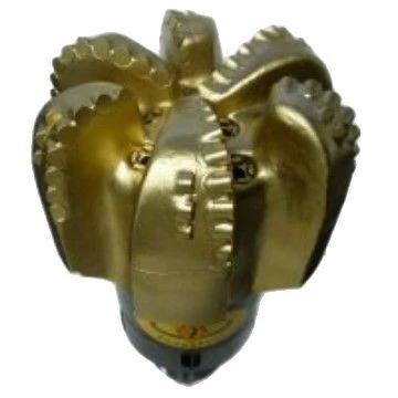
An 8.5-inch oil and gas hole section is best matched by formation response: use PDC for soft, medium, or consolidated rock, and select tricone structure by IADC when impact tolerance or changing lithology matters. Set WOB, RPM, and circulation inside the bit-type window, then reduce dysfunction before adding mechanical load.
Which formation signals should control the bit decision?
Start with the rock interval, not with a preferred catalog family. Soft ground has UCS below 4,000 psi and includes clay, shale, and unconsolidated sand. Medium rock spans 4,000–15,000 psi and includes sandstone, limestone, and dolomite. Interbedded drilling alternates soft and hard layers, so torque and depth-of-cut response can change within a short interval. Those distinctions affect cutter engagement, cleaning demand, and the probability of lateral shock.
A PDC bit is a direct fit for soft, medium, and consolidated formations. It is not a sound first choice for gravel because loose particles can interrupt stable shearing and expose the cutting structure to impact. Review the soft formation drilling window before selecting an aggressive cutter layout. For a medium interval, compare that decision with the medium formation bit criteria. These archive references keep the formation assumption visible during the selection review.
Tricone bits cover the full formation range when the IADC code matches the rock. Milled-tooth 111, 121, and 131 structures belong in soft formations. Insert codes 437 and 447 cover medium rock, while 537 and 547 move into medium-hard service. Code 637 is the hard-formation choice. A code is not decoration in a product description; it expresses the intended cutting structure and must agree with the interval.
How should WOB, rotary speed, and flow be paired?
PDC operation uses 2,000–10,000 lbf/in WOB and 60–300 RPM. For an 8.5-inch-class hole, the available flow range is 250–650 gpm. Treat the three settings as a connected operating envelope. Raising WOB without enough cleaning can pack cuttings around the face. Raising RPM while the bit is laterally unstable can accelerate cutter damage. A stable response at moderate settings is more useful than a high instantaneous penetration rate followed by vibration.
Tricone operation uses 3,000–8,000 lbf/in WOB and 60–120 RPM. The narrower rotary range suits a rolling cutting action rather than continuous PDC shearing. No tricone flow figure is supplied in the approved engineering data, so the hydraulic program must establish that value instead of borrowing the PDC 8.5-inch figure. That boundary prevents a convenient but unsupported number from entering the drilling plan.
| Oilfield bit route | Authorized WOB | Authorized RPM | Formation basis |
|---|---|---|---|
| PDC | 2,000–10,000 lbf/in | 60–300 | Soft, Medium, Consolidated |
| Tricone, milled tooth | 3,000–8,000 lbf/in | 60–120 | Soft; IADC 111/121/131 |
| Tricone, insert | 3,000–8,000 lbf/in | 60–120 | Medium through Hard; IADC 437/447, 537/547, or 637 |
What changes when the interval is interbedded?
Interbedded rock creates a repeated transition between different cutting responses. A setting that produces clean shearing in shale can become too aggressive when the bit enters a stronger band. Conversely, a conservative setting chosen for the harder band may let soft material collect around the face. The practical control is to watch torque, vibration, and cuttings character at each transition, then make measured changes rather than chasing a single target rate.
The interbedded formation selection notes are relevant when offset descriptions show alternating shale and competent rock. PDC can remain suitable, but its limitation must be stated plainly: unstable transitions and gravel-like inclusions can damage cutters even when the average interval appears soft. Tricone may accept impact better, yet a wrong IADC structure can drill inefficiently or wear early.
Connection selection also needs a factual boundary. API Reg 2-3/8″, 3-1/2″, and 4-1/2″ are the stated connection family for PDC and tricone equipment. The final connection must match the bottom-hole assembly. Do not infer connection size from hole diameter alone.
Which failure patterns reveal a poor match?
Bit balling points toward insufficient face cleaning or an overly aggressive response in sticky soft rock. Chipped PDC cutters suggest impact, lateral vibration, or unsuitable gravel exposure. Uneven tricone wear can indicate that the selected structure does not fit the formation or that loading is poorly distributed. A sudden torque change at a bed boundary deserves a parameter review before additional WOB is applied.
Record the setting and the formation response together. A dull condition without operating context cannot separate hydraulic trouble from a structural mismatch. Useful records identify where the response changed, which lithology was present, and whether the change followed WOB, RPM, or flow adjustment. For additional bit-mechanics background, consult PetroWiki drilling references. IADC code context is available from the International Association of Drilling Contractors.
How can the final choice be checked before running in hole?
Confirm that the formation class, bit family, cutting structure, connection, and operating envelope describe the same job. A soft-rock PDC plan should show 2,000–10,000 lbf/in WOB, 60–300 RPM, and, for an 8.5-inch-class hole, 250–650 gpm. A tricone plan should carry an allowed IADC code plus 3,000–8,000 lbf/in WOB and 60–120 RPM. Any missing value should be resolved by the drilling program, not invented in a product note.
Finally, name the exclusion. PDC is restricted in gravel, while a soft-formation milled-tooth tricone is not a hard-rock solution. This simple statement keeps the recommendation auditable. It also gives the driller a clear trigger for revisiting the plan when actual cuttings differ from the expected lithology.