
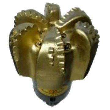
Choose a PDC bit when stable shearing and directional response are priorities in alternating soft and hard beds, then manage transitions with 2,000–10,000 lbf/in WOB, 60–300 RPM, and 250–650 gpm for an 8.5 in hole. A tricone remains an option when impact resistance across changing beds outweighs continuous cutter engagement.
Interbedded drilling is difficult because the bit cannot settle into one failure mode. A soft layer allows deep cutter engagement, then a hard layer suddenly raises contact force. The reverse transition can release stored torque and increase depth of cut. Oil and gas operations also care about borehole quality and predictable response, so the fastest instantaneous rate is not always the best run. The selected bit and controls must limit damaging changes as the face crosses each boundary.
What makes the soft-to-hard transition destructive?
PDC cutters shear efficiently in soft and medium material, but an abrupt hard streak can raise cutter loading before the control system responds. Chipping, heat, and uneven wear can follow if depth of cut is too aggressive. When the bit returns to soft rock, the same WOB may drive the cutters deeper and create torque oscillation. Stable control therefore starts before the boundary, using trends in torque, penetration, and returns rather than waiting for a severe event.
A tricone distributes contact across rolling cones. It can tolerate changing rock when its tooth structure matches the harder part of the interval, but that compromise may be less efficient in the soft bed. Milled teeth suit soft formations. Inserts suit medium through hard rock. An insert tricone chosen for the hard layers can cross softer beds, yet it should not be expected to cut them like a dedicated soft-rock structure. Compare the setting with the interbedded formation archive and the oil and gas drilling archive.
How should a PDC operating window be used?
The approved PDC range is 2,000–10,000 lbf/in WOB and 60–300 RPM. For an 8.5 in hole, flow is 250–650 gpm. Those are boundaries, not instructions to operate all controls at their upper values. Begin with a combination that produces stable torque and identifiable cuttings. As a hard bed approaches, reduce the chance of a sudden depth-of-cut increase by moderating the control that is driving cutter engagement.
Change one input at a time. If torque rises with falling penetration, extra WOB may intensify the problem. If returns become fine and temperature response increases, cleaning or recutting may be involved. Flow must stay inside 250–650 gpm for the stated 8.5 in reference, but more flow cannot repair a chipped cutter. The rig team should separate hydraulic symptoms from cutting-structure damage.
| Interbedded decision | PDC reference | Tricone reference | Transition concern |
|---|---|---|---|
| Soft bed | 2,000–10,000 lbf/in; 60–300 RPM | Milled teeth; 3,000–8,000 lbf/in; 60–120 RPM | Excess depth of cut or torque release |
| Medium-hard bed | Keep within the PDC ranges above | Insert teeth; IADC 537 or 547 | Impact and cutter loading increase |
| 8.5 in hole cleaning | 250–650 gpm | No flow value supplied | Do not invent a tricone flow target |
When is a tricone the better compromise?
A tricone becomes attractive when the sequence produces repeated cutter-impact damage or when rolling contact gives a more controllable response. Use 3,000–8,000 lbf/in of diameter and 60–120 RPM. Choose the tooth family from the rock that controls durability. IADC 537 or 547 is permitted for medium-hard insert service; 637 is for hard formation. A soft milled-tooth code such as 111, 121, or 131 is not the right answer if hard beds dominate failure.
The limitation is efficiency. An insert structure that survives the hard layer may drill the soft layer less aggressively. Bearings and seals also add failure points that PDC does not have. The choice should come from dull evidence and downhole response rather than a general claim that one type always handles interbedding better.
The PetroWiki drilling reference can support terminology, and the IADC is the allowed source for classification context. The numerical limits in this article remain those stated in the project fact table.
Which dull features explain the transition?
On PDC, map chipped cutters, worn flats, and any asymmetric damage by blade and radius. Damage clustered on shoulder cutters may correspond to gauge or transition loading. A smooth wear flat across the face suggests a different mechanism from isolated impact chips. Relate the location to torque events and the depths at which formation changes were observed.
On tricone, inspect teeth, cone tracking, bearing condition, and gauge. A hard layer can chip an unsuitable milled tooth. An abrasive band can reduce outer inserts and change hole size. Do not average these features into a single “worn” label. The next bit decision depends on which layer caused which damage.
How can the next interbedded run be steadier?
Build a depth-based record of WOB, RPM, flow where applicable, torque character, penetration, and cuttings. Mark the first sign of each transition. If the data shows repeated shocks at the same rock boundary, plan a controlled parameter change before that depth on the next run. This is more reliable than reacting after the event.
PDC is not recommended for gravel, and that limit remains relevant if an interbedded description hides loose coarse material. Tricone selection also has limits because one tooth structure cannot be optimal for every layer. The best program accepts a controlled compromise, protects gauge and cutters, and uses the recovered bit as evidence for the next interval.