
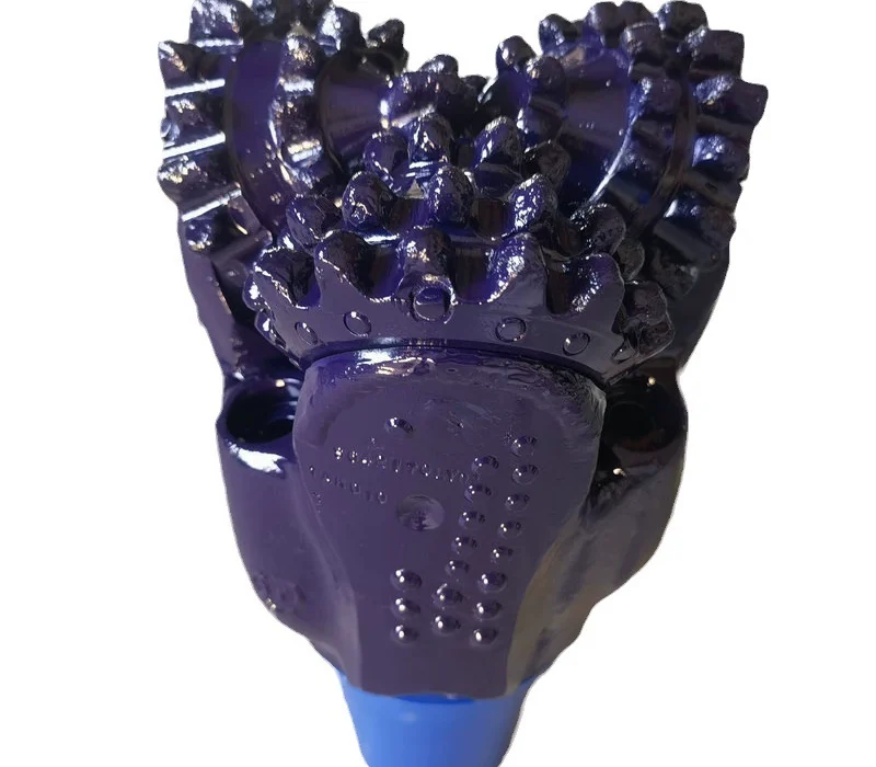
A 3-1/2-inch API Reg label can confirm one oilfield connection family, but well-completion tool choice must follow the cleanout or drill-out target. Milling and workover bits fit this application. Verify geometry, surrounding rock, circulation path, and stop criteria; obtain WOB, RPM, and flow from the approved completion procedure.
What is the completion tool expected to remove?
Completion work can involve clearing an internal restriction, dressing material, or preparing access through a downhole target. The first selection question is therefore functional: what material must be cut, and what must remain undamaged? Milling and workover bits are the listed families for well-completion service. Their application fit is established, but a specific face, blade, or cutter arrangement still requires verified product data.
The surrounding interval may also matter. Below 4,000 psi, the Soft class covers clay, shale, and unconsolidated sand. Consolidated formation is well-cemented sedimentary rock. If the completion assembly moves beyond the intended target, contact with either condition can change torque, returns, and wear. Use the soft formation behavior summary and the consolidated rock definition to describe that possibility.
A completion tool is not selected by formation alone. The target profile, allowable outer diameter, connection, circulation route, and recovery plan remain controlling inputs. The honest limitation is that the approved facts do not provide a universal milling WOB, RPM, or flow range. Those settings belong in the well-specific procedure after the assembly is confirmed.
How are connection and clearance checked?
API Reg 2-3/8″, 3-1/2″, and 4-1/2″ are identified for PDC and tricone connections. They can help recognize compatible oilfield components, yet they do not automatically define a completion mill interface. Verify the exact connection on the selected tool and string. Never derive it from casing description or target diameter.
Clearance must permit deployment and a return path for removed material. The source facts give no completion-tool blade count, cutter size, or bypass dimension. Leave those fields unfilled until a product drawing confirms them. Unsupported detail creates a false sense of precision and can hide a genuine fit issue.
| Completion decision gate | Known engineering fact | Required action |
|---|---|---|
| Tool family | Milling and workover fit well-completion | Choose a verified intervention design |
| Soft exposure | Below 4,000 psi; clay, shale, unconsolidated sand | Watch for changed returns and contact |
| Cemented interval | Consolidated is well-cemented sedimentary rock | Define the formation-contact limit |
| Mechanical and hydraulic settings | No completion milling range is supplied | Use the approved job program |
Why should circulation be planned with the cutter?
Removed fragments need a controlled route away from the face. If debris remains in contact, the tool can recut it, obscure progress, and develop an erratic response. The completion engineer should pair tool geometry with the chosen circulation and recovery method. Because no general flow value is authorized for this application, the hydraulic program must calculate or approve the required setting.
Return character can identify a change in contact. Material matching the target indicates continued drill-out. Shale, sand, or cemented rock fragments may show that the tool has reached formation. That observation should connect to a prewritten action: stop, reduce contact, circulate, or reassess. The action values themselves must come from the completion procedure rather than an unrelated drilling range.
The well workover application notes provide a related intervention context, but completion has its own target and acceptance criteria. A tool that is broadly described as a workover cutter still needs a completion-specific envelope and debris strategy.
Which symptoms indicate that the run is no longer controlled?
Unsteady torque can mean intermittent target contact, trapped fragments, or an eccentric cutting path. Declining advance with similar returns may signal dulling. Changing returns can identify formation contact. Uneven cutter wear can point to poor loading across the face. None of these observations should be answered automatically by adding WOB.
Pause when the evidence no longer matches the stated target. Review the depth, returned material, torque trend, and the last parameter change. The tool may have completed its task or entered a condition outside its selected geometry. A clear stop criterion protects the completion hardware and makes the final report easier to audit.
Completion and drilling terminology can be checked at PetroWiki. Connection and equipment standards information is available through the American Petroleum Institute. Project drawings and the approved well procedure remain the controlling sources for the actual run.
Before deployment, compare the maximum tool envelope with every known restriction in the completion. Include the cutter body, connection shoulder, and any gauge feature rather than recording only nominal diameter. A tool can pass one component and still interfere with another. The clearance review should name the drawing or measurement used.
After recovery, identify which material remains on the face. Target debris, formation fragments, and packed fines lead to different conclusions. Clean the tool without damaging evidence, then document cutter loss, eccentric wear, connection condition, and measured gauge. This closes the loop between the planned endpoint and the actual contact.
How should the completion recommendation be written?
Identify the target material, tool family, verified geometry, connection, deployment clearance, debris route, possible formation exposure, and stop condition. Mark unverified values as open. Do not populate cutters, blades, WOB, RPM, or flow merely because a specification template contains those fields.
State the operating limitation in direct language: the available application table assigns milling and workover bits to well completion, but it gives no standard parameter window for them. A completion engineer must approve those values. This separation between verified compatibility and job-specific operation prevents PDC, tricone, button, or drag figures from being used outside their defined mechanisms.